3. General properties of ether (vacuum)
Modern researchers interpret a physical, homogeneous continual medium (gas, liquid, solid) as matter, filling space uniformly and three-dimensionally and possessing an ability to transmit perturbations (oscillations) with steady speed. The properties of a medium define the perturbations propagation velocity in it. Continual media possessing essentially different expedients of perturbations transmission are known. One of them is noted for by transmitting perturbations along the line coincident with the direction of propagation. Another type of medium is capable to transmit perturbations with the vector of displacement in the direction of the propagation and with the vector of displacement oriented along the normal line to the direction of propagation. There is the third type of medium, in which the displacements happen in mutually orthogonal to each other orientations and to the direction of propagation. The first medium represents gas (liquid), the second - a solid body. The properties of the medium of the third type - ether (vacuum) - have not been fully determined so far. It is known, that ether is characterized by physical constants: velocity of waves propagation, dielectric constant and magnetic conductivity.
Investigations of the processes of radiation, propagation and reception of electromagnetic waves, carried out after J.C. Maxwell, have shown, that ether has a specified value of wave impedance Z ~ 377 ohms [3]. Observations on the process of a vacuum-processed condenser charge, current feed into a solenoid, allow one to conclude, that electromagnetic processes have inertia in ether. The established facts and phenomena allow one to state, that ether is a specific medium differing fundamentally from gas, liquid and solid media.
One of the most remarkable properties of ether is the fact that it does not offer resistance to a uniform motion of a physical body. For example, in material (possessing density) media, fundamental particles (electrons etc.) are constantly in mutual motion. A stable state of macro-objects, their fixed relative position can be maintained for an extremely long time. For example, the determined age of some terrestrial rocks and meteorites is 3.8-4.7× 10⁹ years [34]. All this time a motion, for example, of electrons around atoms composing a crystal lattice of minerals in these rocks and meteorites, takes place without a change of their orbits and deceleration of their circulation velocity around atomic nuclei. From the investigation results of astronomers we also know, that the light from the most remote galaxies comes to us over a period, estimated at millions light years. At any noticeable absorption of light by ether, we would not be able to observe these far galaxies.
Observations of electromagnetic waves and light propagation in ether give the most complete data about its properties. It is known that an electromagnetic wave is a recurrent change of electric and magnetic fields in time and space. This change spreads in all directions from the area of space where vibrations originate [3]. An electromagnetic wave, propagating in space is described by mutually perpendicular intensity vectors of the electrical …
and magnetic Ќ fields. The intensity vectors … and Ќ vary synchronously and perpendicularly to the wave propagation direction. Perpendicularity of the vectors E, H and propagation direction causes "shear nature" of an electro-magnetic wave. The vectors E and H remaining mutually perpendicular may be oriented arbitrarily in a plane normal to the propagation direction.There is also a very important property of electromagnetic waves - their polarizability. Light being an electromagnetic wave has properties of polarizability and shear nature (transverse nature). Light can have linear, elliptic and circular polarizations [35]. In the first two cases it is possible to determine the orientation of the vectors … and Ќ. It is impossible to fix the direction of the vectors at circular polarization. Chaotically polarized (natural) light is also present. A physical medium can change the light polarization degree, for example, by distinguishing linear-polarized light in chaotically polarized one, and also by changing a light polarization type, - linear to elliptic, circular etc.
As the light propagates in liquid and solid media some more effects arise - pleochroism (dichroism) and a manifestation of optical activity (a rotation of polarization plane) [36, 37]. The reason for pleochroism is anisotropy of light absorption, namely, the light component, polarization vector of which is oriented perpendicularly to aligned structural elements of medium, is absorbed.
At present many types of natural light polarizers have been developed using the pleochroism effect [38]. Minerals and substances composed of dissymmetric molecules that have neither a centre nor a symmetry plane but only an axis possess an optic activity. Using polarized light for studying a substance has a long history. It began to be used most intensively after William Nicol had introduced polarizers in a microscope in 1828.
The laws of propagation of polarized elastic waves have not been studied as well as those of light waves. In an unlimited continuous homogeneous isotropic solid body, two types of elastic waves may propagate - longitudinal and transversal (shear). Phenomena, similar to the light propagation polarization, are observed in solid bodies during propagation of elastic shear (transverse) waves. Their polarization vector is directed along the normal (in a generally case) to the propagation direction, similarly to the vectors … and Ќ in electromagnetic waves. A study of the laws of polarized elastic waves propagation will help to reveal analogies and peculiarities of electromagnetic waves propagation.
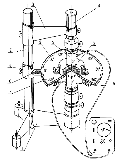
A new method named the acoustopolarization method was developed for studying shear waves propagation particularities in a solid body [39]. The method is intended to detect elastic anisotropy, to determine the number and the spatial orientation of symmetry elements, type of symmetry and values of elasticity constants. The method has been approved on media of traversal-isotropic, orthorhombic and other types of symmetries. A basic scheme of observations realized according to this method, does not differ from the polarization observations in optics [40]. Acoustopolarization measurements are carried out by a specially designed device, named acoustopolariscope, Fig. 1 [41]. It comprises a base (1), a pole (2) and a bracket (3). A rod (4) moves in the bracket. In the lower part of the rod and at the base, a transmitter and receiver (5) are fixed in axial position. The sample (6) is fastened on rotating platform (7). The rotating platform is placed on the additional bracket (8) and has a scale (9) for calculating angles of rotating with respect to the mark (10). The basements of transducers have scales and marks in order to inspect rotating angles. Tight contact of the sample and the transducers is reached by springs in the basements. The signal transmitted through the sample is observed on an ultrasonic device. This device has a graded attenuator of the input signal.
Our method of acoustopolarization measurements follows that of [41]. Before the first stage of measurement, the polarization planes of transducers are brought in line (VP-position). The sample is placed between the transducers and fixed in the holder (8, Fig.1). The coupling medium is put on the working surfaces of the transducers. In a sequence of measurements, the rotating platform (6, Fig. 1) is rotated through 360 degrees, and signal amplitudes are measured on the screen of a recording device.
The second stage of measurements is conducted with the polarization planes of the source and receiver intersecting at 90 degrees (VC-position). Again, the measurements are conducted through a 360 degrees rotation of the sample. As a result of these measurements, we obtain acoustopolarigrams of anisotropic samples for parallel (VP) and intersecting (VC) directions of transducer polarization.
Observation by acoustopolarization method in practice requires the use of transducers transmitting purely shear, linear-polarized shear waves into a sample [39]. In addition, it should be noted that the success of measurements depends on the choice of the coupling medium, which makes the contact between the transducers and the sample. As a coupling medium, we use a highly viscous solution of non-crystallised sugar. Such a coupling medium is very effective: its viscosity can be regulated, it provides the rotation of transducers with respect to the sample, ensures good repeatability of the results.
Fig. 1. Design of acoustopolariscope with the rotating platform (Pat. No. 1281993, USSR). 1 - base; 2 - pole; 3 - bracket; 4 - travelling rod; 5 - transducers; 6 - sample; 7 - rotating platform; 8 - additional bracket; 9 - angle scale; 10 - mark.
The acoustopolarigram obtained by parallel (VP) vectors of polarization, allows to judge, for example, the presence of a linear acoustic anisotropic absorption (LAAA) effect and, accordingly, a preferred orientation of structural elements [39]. The acoustopolarigram obtained by VC position allows to making the conclusion about the presence and number of symmetry elements in the given cross-section of the sample, and about their orientation in space.
In Figure 2 experimental acoustopolarigrams for different materials, illustrating particularities of shear waves propagation in them are given. The cubic sample C-t-5 is made of a silicate glass block. It represents a practically isotropic medium (the velocity of a longitudinal wave is 5.77 km/s, of a shear wave - 3.41 km/s). Three pairs of acoustopolarigrams obtained in the directions 1-1', 2-2' and 3-3' for three sides of the sample (Fig. 2 ) indicate it. The VP acoustopolarigrams are close by shape to an exact circle. The VC acoustopolarigrams are small in size and have no precisely expressed maxima. Acoustopolarigrams of a wooden sample have quite interesting shapes (Fig. 2b). The VP acoustopolarigrams, obtained for all three pairs of sides of the cubic sample, differ radically from theoretically calculated ones. An analysis displays, that the amplitude of shear waves at polarization vector, directed along the normal to the wood fibres, is 2-5 times less, than that at the vector orientation along the fibres. Thus, there is an intensive absorption of waves energy when the polarization vector of a shear wave is directed across the fibres. A similar property - to absorb waves in various ways, called pleochroism (dichroism), - is observed during the propagation of polarized light through some minerals, such as tourmaline, kunzite, cordierite etc. [36].
This property, called an effect of linear acoustic anisotropic absorption of shear waves (LAAA), is observed rather often in textured rocks [42]. In wood LAAA is accompanied, as follows from the shape of VC acoustopolarigrams (Fig. 2b), by an elastic anisotropy. One of the elastic symmetry elements is directed along the axis of the wood ring structure, and another - along the normal to it. Even more considerable manifestation of the linear acoustic anisotropic absorption is observed in a sample of mineral microcline, Fig. 2c. The cubic sample was cut out from microcline in such a manner, that its crystallographic axis [001] coincided with the normal line 1-1' to the side (1), and the axis [010] - with the normal line 2-2' to the side (2). The VC acoustopolarigrams, obtained at crossed vectors of polarization, show that elements of mineral's elastic symmetry are practically perpendicular to the sample sides. The indexes of the linear anisotropic absorption effect for the first and third pairs of sides are very great (D1 = 0.90 and D2 = 0.93 respectively [41]). The most natural explanation of LAAA manifestation in the microcline sample is, that this mineral has perfect cleavage in two directions. The cleavage planes form plane-parallel spatial lattices, at which the waves are absorbed.
Acoustopolarigrams in the direction 1-1' (Fig. 2d) were obtained using a cubic sample of a synthetic quartz monocrystal (trigonal syngony). The rotary axis [0001] of the third order passes in the same direction. Accordingly, on the VC acoustopolarigram, 6 successive minimums with a step of approximately 60o, - two minimums for each symmetry plane are noticeable. The VP acoustopolarigram consists of three petals. Acoustopolarigrams, obtained in the directions 2-2' and 3-3', show the presence of two symmetry elements. Figure 2d shows, that the acoustopolariscopy method can be used to study wave processes in media of low-symmetry systems: triclinic, monoclinic etc.
The stated examples illustrate some singularities of shear waves propagation in composite media. They confirm the presence of all three polarization forms, - linear, elliptic and circular during shear waves propagation in anisotropic media.
The value and direction of vector Ђn that describes the medium motion in the wave is expressed by equation:
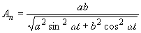 , (5)
, (5)
where a and b are major and minor axes of the ellipse of the medium's particles shift respectively; w is a circular vibration frequency; t is time.
If a = b, polarization of the shear vibrations will be circular. If a = 0 or b = 0, polarization of the vibrations will be linear.
Similar phenomena can be observed as light waves propagate. Every photon represents a single wave packet (soliton) of a certain frequency. The direction of the ether particles shift is along the normal to the photon propagation. As the photon passes, it may excite circular, elliptical or linear shifts in the ether medium. In this case the photon is said to have circular, elliptical or linear polarization. The forms of the ether particles shift during the photon passage are similar to those in Fig. 3.
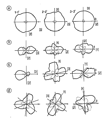
Fig. 2. Acoustopolarigrams of cubic silicate glass samples ( ), wood (b), microcline monocrystal (c), synthetic quartz (d)
in three mutually perpendicular directions 1-1', 2-2', 3-3'. VP - solid lines; VC - dotted lines.
There are some devices, for instance polarimeters, that enable one to identify one or other polarization type in the total chaotically polarized flux of the sunlight [37]. The ability of electromagnetic waves to take different polarization forms is widely used when investigating properties of various substances, in radio electronics, radiolocation, astronomy etc. [35, 37, 43, 44].
Outcomes of an analysis of a large number of solid media acoustopolarigrams, mainly minerals and rocks, and known data from optical polarization observations practice [35-44], allow one to make a primary classification of common and distinguishing phenomena accompanying the propagation of polarized electromagnetic and acoustic waves. Mathematical description of the following phenomena is adequate for the two types of anisotropic heterogeneous media in which waves propagate:
However, the following singularities are characteristic of each of these types:
Thus, during the propagation of electromagnetic, light and elastic shear waves many similar and close phenomena, indicating the existence of common elements in the structure of both solid body and vacuum are observed.
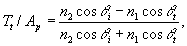
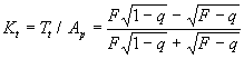
The cited enumeration of common and distinguishing phenomena and indications of interaction with media of electromagnetic and acoustic waves is not complete. In addition let us consider the expressions for reflection and transmission factors of a past and reflex flat homogeneous light wave incident on a flat surface, that divides two media, differing in optical properties [47]. For a wave component, which vector of polarization is parallel to the contact plane of the media, the transmission factor is equal to:
where Tp is the amplitude of the wave, transmitted into the second medium; Ap is the amplitude of the wave, incident on the media interface; n1 is the refraction factor in the first medium, n1 = C/V1; n2 is the refraction factor in the second medium, n2 = C/V2; C is the velocity of light propagation in ether; V1 is the velocity of light propagation in the first medium; V2 is the velocity of light propagation in the second medium; q i is the angle of incidence of the wave ray in the first medium; q t is the angle of incidence of the wave ray in the second medium. For the reflected wave the corresponding factor is equal to:
where Tt is the reflected wave amplitude.
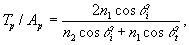
Now we shall consider the reflection and transmission equations for an acoustic shear homogeneous plane-polarized wave with a flat front, incident also on a flat interface of two solid media, differing in acoustic properties of solid media. According to [50] for a wave with a polarization vector lying in the plane of interface plane (SH-polarization), the transmission and refraction factors look like:
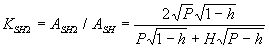 , (8)
, (8)
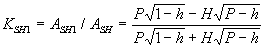 , (9)
, (9)
where ASH2 is accordingly the amplitude of the transmitted wave, ASH1 is the amplitude of the reflected wave; ASH - is the amplitude of the incident wave; ђ = (VS12/VS22)2 is the ratio of the square velocity of a shear wave propagation in the first medium VS1 to the velocity of the same wave propagation in the second medium VS2; h = sin2b , where b is the angle of incidence of the shear waves ray in the first medium; H = r 2/r 1 is the ratio of density r 2 in the second medium to the density r 1 in the first one.
Using the Snellius equation sinq i/V1 = sinq t/V2 and also the expressions q = sin2q i, F = (n1)2/(n2)2 the equations (1) and (2) can be brought into the form, similar to the equations form (3), (4):
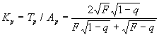 , (10)
 .
.
Analysing jointly the equations (3), (4) and (5), (6) it is possible to note their rather close structure. Except for the parameter H = r 2/r 1 (r 1 is a density in the first solid medium, r 2 is a density in the second one), these pairs of equations are equivalent. The parameter Ќ in the reflection-transmission equations (5), (6) of light at the interface of optically distinguishing media is absent. This implies the conclusion that ether and optically transparent bodies (gases, fluids, solid bodies) do not differ in the density parameter, but only in the waves propagation velocity in them for electromagnetic waves. To put it otherwise, ether has neither density nor mass, which physical bodies have. Ether is the basis of electromagnetic waves propagation inside physical media also. As is known, the velocity of light propagation in gases, fluids and solid bodies is lower, than in vacuum [2].
On the basis of that, it is possible to assume, that in physical, perceptible (detected by physical devices) media as photons bend around atomic structures they have to overcome an additional distance, which causes the decrease in the velocity of waves propagation.
Let us also note, that concerning the laws of light reflection-transmission on the media interface the complete balance of energy eliminating the possibility of any additional "longitudinal" light waves is observed [47]. An enumeration of other phenomena and effects including piezo- and thermo-electricity, mutual electro-elastic effects are described in [43, 51, 52]. Summarizing the outcomes set forth the following should be assigned to general properties of ether (vacuum):
The following model of ether meets to the utmost all enumerated and known properties, the concepts of I. Newton, MacCullagh, J. Maxwell and W. Thomson.
1. Ether called further as ethereal medium, consists of alternate corpuscles of two, opposite in sign, kinds. The alternate corpuscles, opposite in sign, are attracted to each other, forming a homogeneous space, in which, in a non-perturbed state, each of the alternate corpuscles adjoin an alternate corpuscle, opposite in sign. Opposite in sign corpuscles are attracted to each other with great force.
2. Particles opposite in sign composing the ethereal medium move relative to each other completely without friction. The ethereal medium consisting of these particles is a medium of a special type. Linear, circular and other kinds of a motion, shear strains etc. can exist in it indefinitely long. This medium has no density in the ordinary sense. It has definite electromagnetic properties.
3. Any physical substance (matter, molecules, atoms), possessing a mass (density), is permeable to the ethereal medium. Any physical substance can move without friction in the ethereal medium.
4. The inertial forces originate when any physical substance interacts with the ethereal medium only at acceleration or deceleration of motion. A uniform motion of a local physical body deforms the ethereal medium, changing the distance between the oppositely charged, conjunct with great force particles of the ethereal medium, which close up again after the body has transmitted.
5. An acceleration of a local physical body creates inertial perturbations in the ethereal medium. The greater is acceleration of the body, the greater are the perturbations. The greater are the mass and acceleration of a physical body, the greater are the perturbations it induces.
6. The ethereal medium, to some extent, is bound (anchored) by great, on an astronomical scale, physical masses (for example, galaxies), as their presence and movement causes the greatest strain of the ethereal medium.
7. The waves propagating in the ethereal medium represent different kinds of shear strains, in which the displacement of the ethereal medium particles happens in the direction, perpendicular to the propagation direction. The enumerated theses require additional evidence and, at the same time, allow one to develop a physically adequate model of the ethereal medium structure. Below we present the evidence of the formulated theses.
`